
Week 06 : Electronics design
the assignment for this week are:
The group assignment
- Use the test equipment in our lab to observe the operation of a microcontroller circuit board.
The individual assignment
- We have to redraw the echo hello-world board , add (at least) a button and LED (with current-limiting resistor) check the design rules, make it, and test it.
- We have to mill and stuff the board and see if it is working
Groupe Assignement
For this part of , here's the direct link for the assignment
Individual Assignement
Since it's been quite a while since I literally touch anything related to physics and anything, so I was little bit lost at first
However, with the help of our instructor, I kinda had some mind refreshments afterwards
As a start, I had to search online about how things are working properly , I have the basics af course but I only had to refresh my mind and to know more about what I'm going to do .
- So what do we know about electrec circuit so far ?
- Electrical Charge
- Components
- Circuit Diagram
- Circuit Design
Electrical circuit is an interconnection of electrical components. An electrical circuit consists of batteries, resistors, inductors, capacitors, switches or transistors. An electrical network consists of a closed loop. A circuit is a closed path where electrons flow in a wire. As long as the copper wire is allowed to itself, the electrons drift between the atoms but never leave the copper.
Electricity is the movement of electrons. Electrons create charge, which we can harness to do work. Your lightbulb, your stereo, your phone, etc., are all harnessing the movement of the electrons in order to do work. They all operate using the same basic power source: the movement of electrons.
Voltage is the difference in charge between two points.
Current is the rate at which charge is flowing.
Resistance is a material's tendency to resist the flow of charge (current).
So, when we talk about these values, we're really describing the movement of charge, and thus, the behavior of electrons. A circuit is a closed loop that allows charge to move from one place to another. Components in the circuit allow us to control this charge and use it to do work.
Sources:
Voltage current resistance and ohms law
It's so informativ and a totally good start
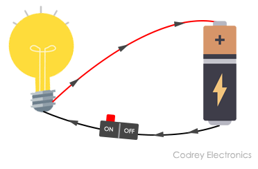
Generally a circuit diagram is a visual display of an electrical circuit. There are mainly two types of circuit diagrams:
Pictorial: Pictorial diagrams are made using basic images. This type of diagram gives a visual representation to audience which is less technical.
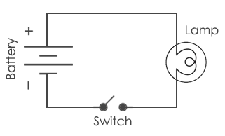
Schematic: This kind of diagrams are drawn using standard industrial symbols.
It's more like the logical representation of a circuit.
These diagrams are used for the representation of a circuit to an electrician or any other technical audience.
As the first part of this weeks assignment, we had to copy Neil's Hello-world board, in other words, not that much work when it comes to being creative!!
- Step 1: Preparing the surface for work
- Download an EDA software
- Download the library of Components
So for this part we had to use softwares that are made for this part of job.
I choose to work with EAGLE, which is an electronic design automation (EDA) software (It's a part of the AUTODESK family and you can open it using your account)
PS: You're not going to do a big deal since you're going to marely copy Neils original work, the real challange is when adding the new components [LED and BUTTON(at least)]
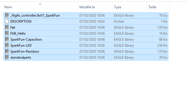
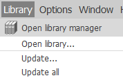
Once you downloaded Eagle, you need now to download the library of the electronic components that you're going to use for designing the Hello-Board
- Step 2: The Workflow
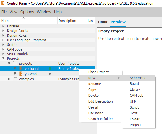
- Add a new project
- And now, start drawing the Schematic of your desired circuit
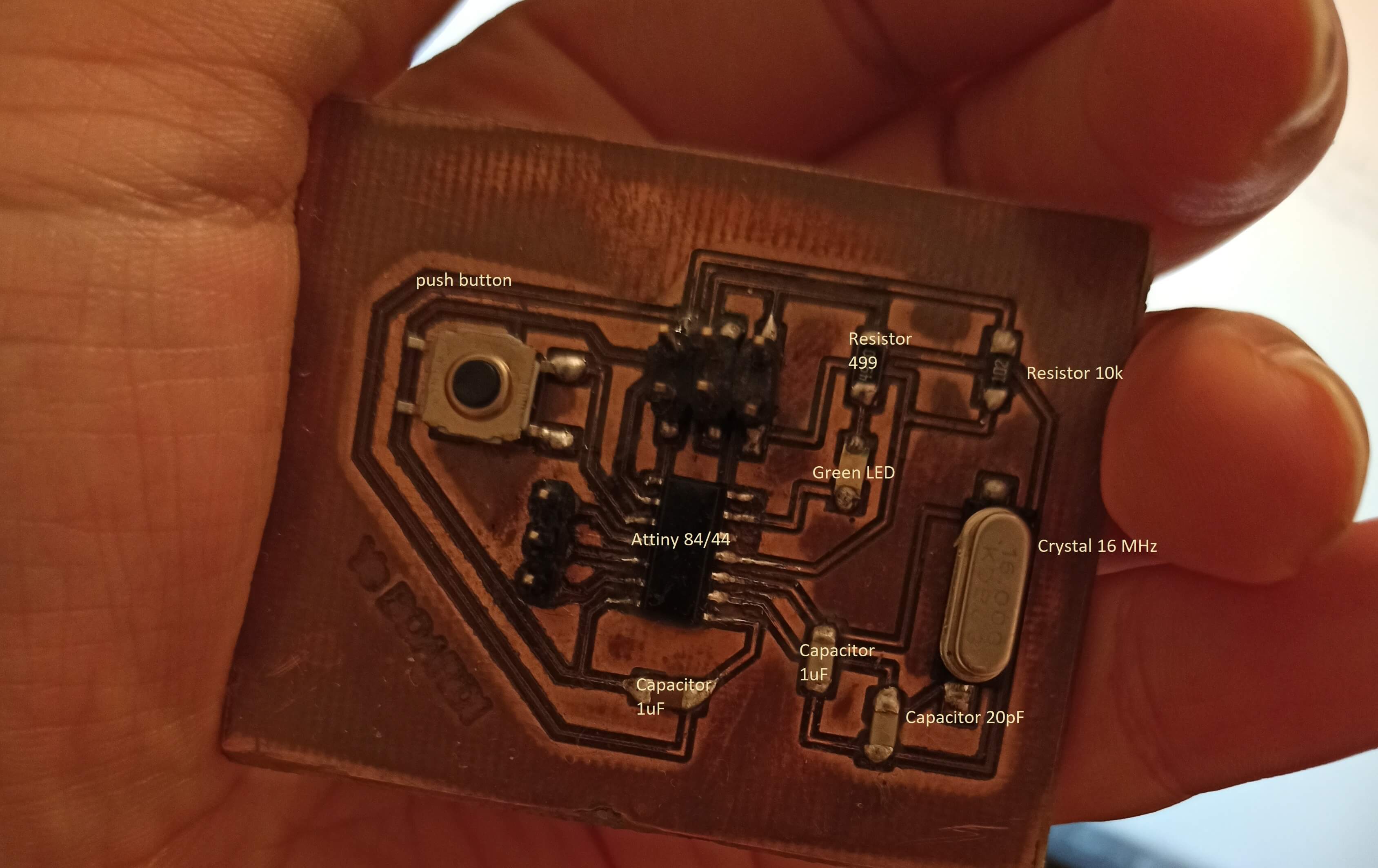
- ATtiny44-SSU
- 16 MHz SMD Resonator
- GREEN LED 1206
- AMP QUICK CONNECTOR M03
- GND: Ground
- VCC: Power supply
- UNPOLARIZED CAPACITORs 1206 (1µF and two 20pF)
- 2 RESISTORS 1206(499Ω/1kΩ):
- AVRISPSMD:to program the board
- 6MM_SWITCH6MM: OMRON Switch
- >Arrange and route the Board
- Check the Design rules and Errors
-
You should hide most of the layers and leave only the top, the bottom, pads and dimensions
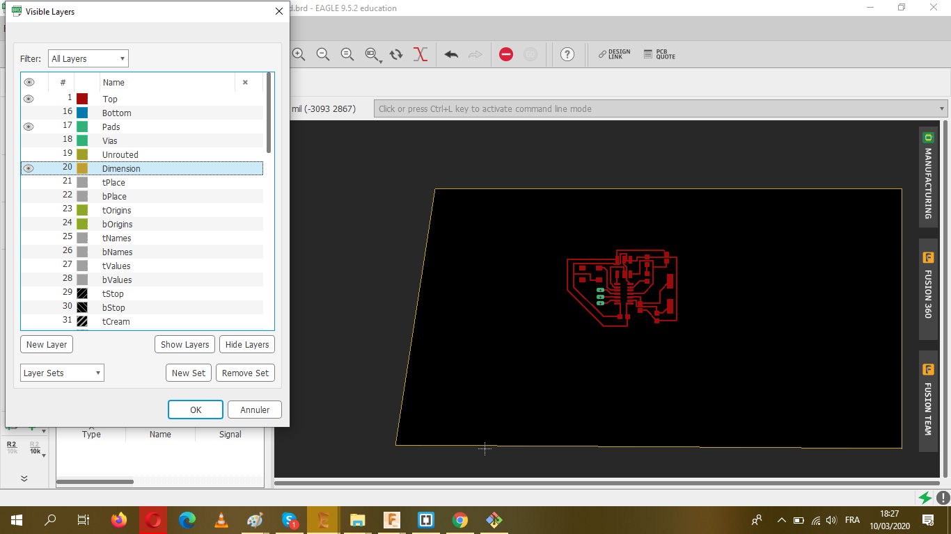
- Give a proper border and export it as a PNG file
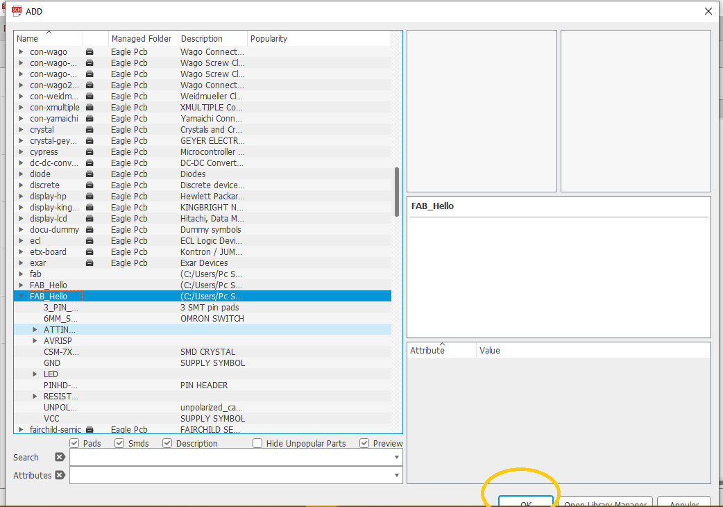
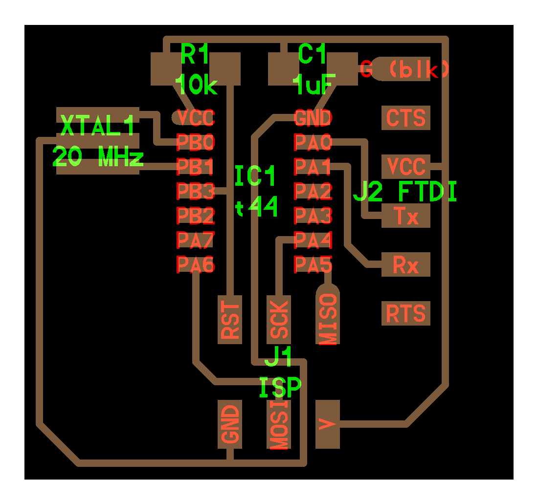
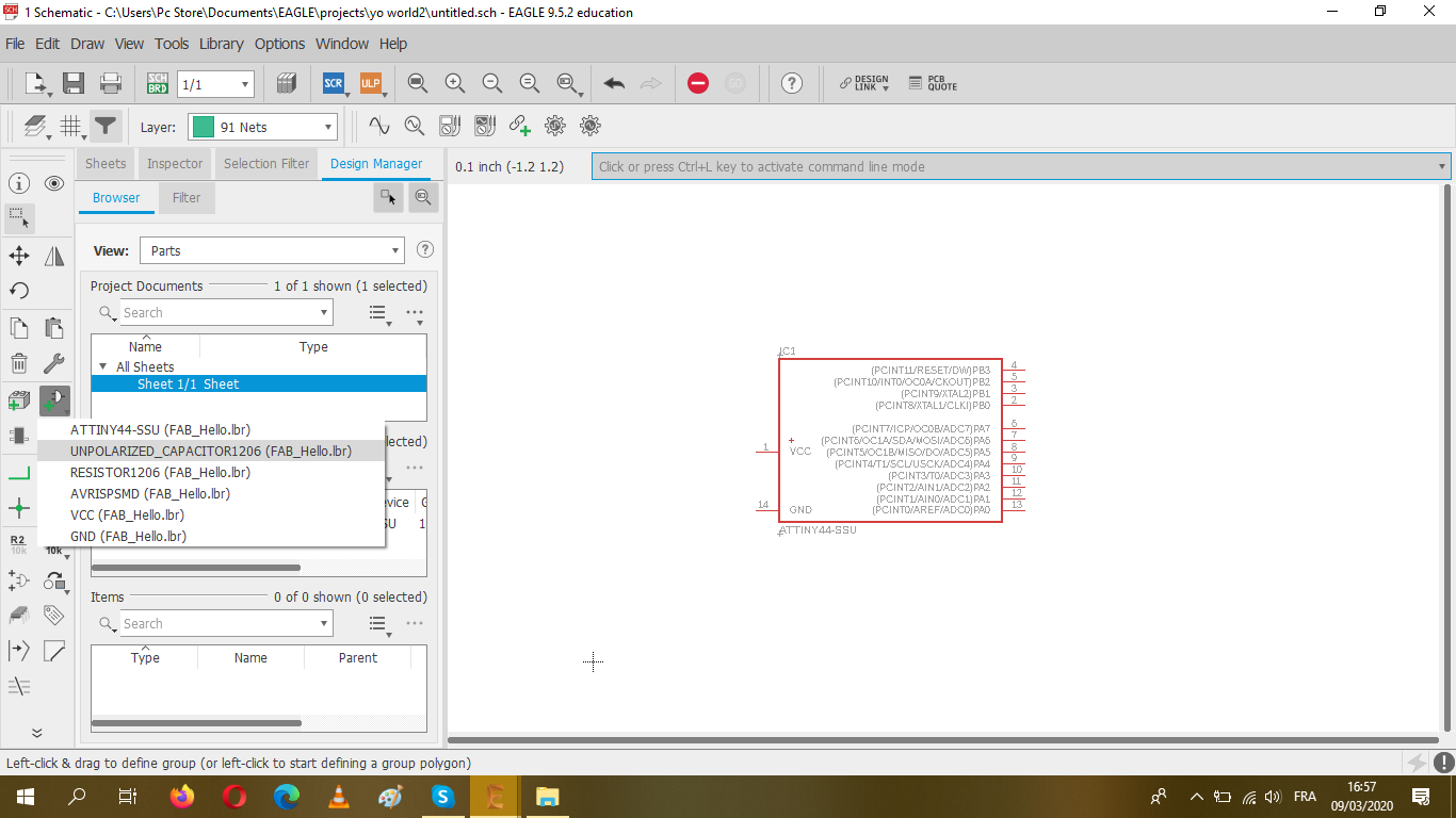
So as you can see, here's the components that I used for my board from the libraby!
All what you have to do next, is linking the components with each other.
I started with the ATiny44 as the central component in the schema of my circuit, then I started linking it with the rest of the components.
Here's what I used to draw my schema;
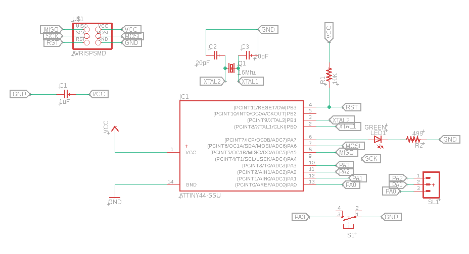
It's much easier to connect the components using "LABEL" without creating any mess while moving out wires from place to place.
And this is how the final Schematic looks like:
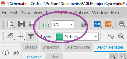
You can generate the corrspondant board of you schematic by clicking on the top SCH/BRD tab
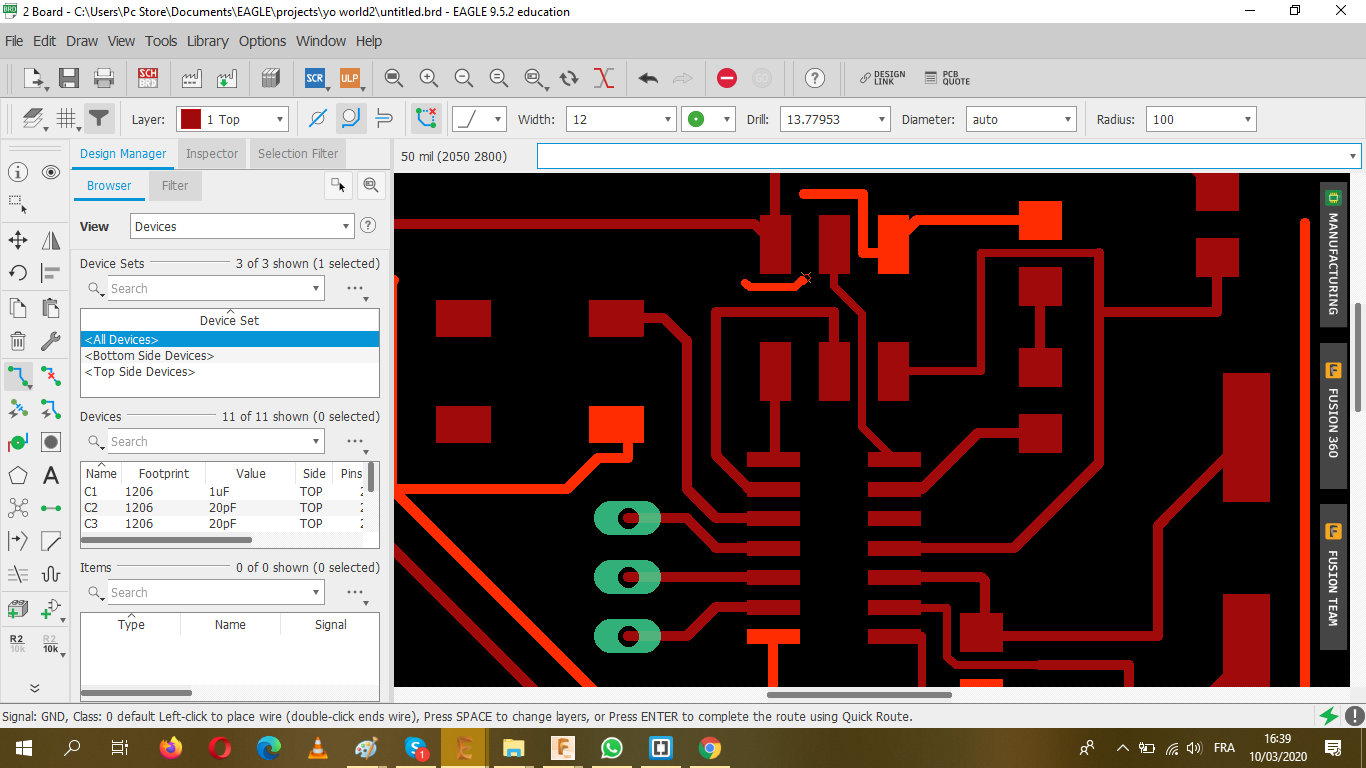
Here's where the footprints of Schematic are present and you need to manually arrange all the components in a way that it looks like a puzzle so when routing my wires don't overlap each other.
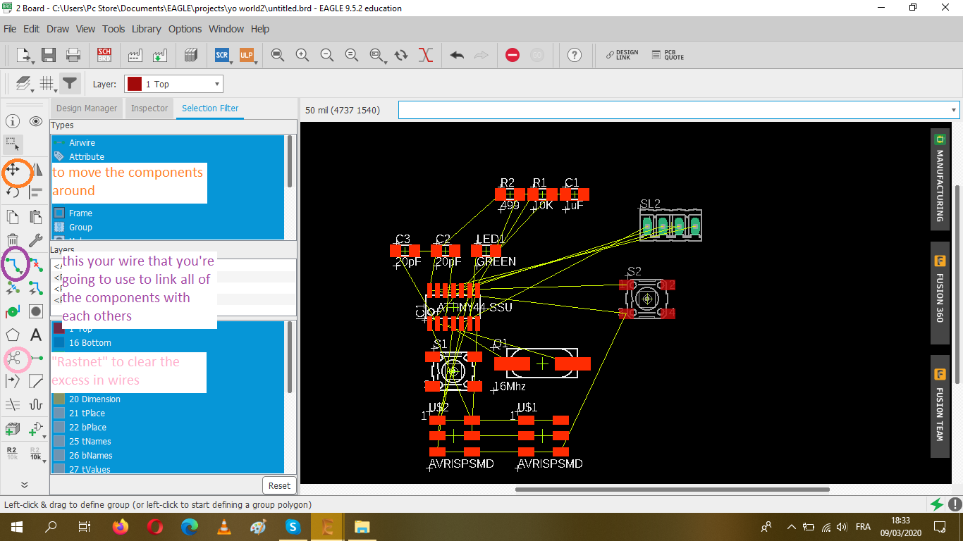
While placing the components and solving "the puzzle" use the Rastnet tab to clear all the excess air wires.
You have to set the parameters after selecting on DRC,you have to edit whatever you want (the clearance, the size) depending on you designs requirements
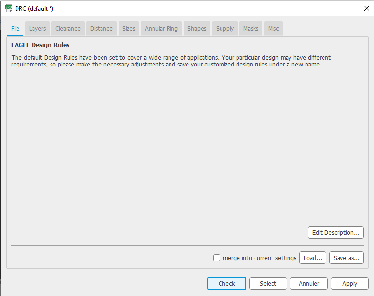
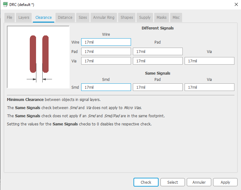
While making your Circuit you have to check everytime for Errors!
.png)
.png)
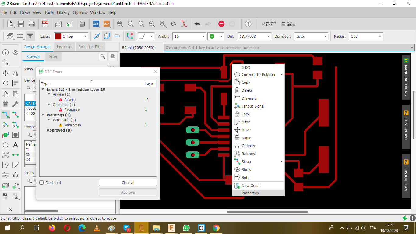
Here's some things that you need to do to make your board less complicated while connecting the air wires:
And finally I'm done!
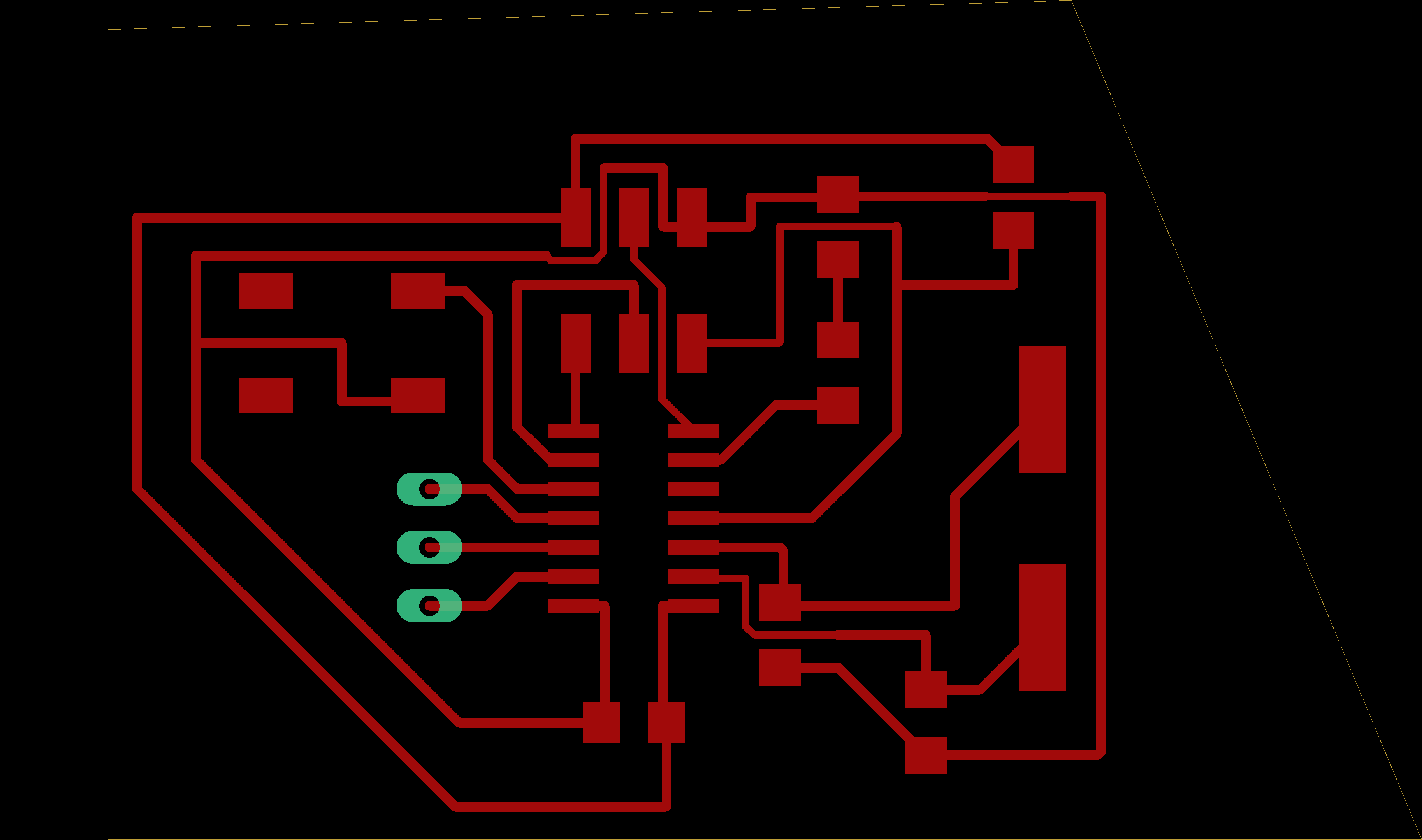
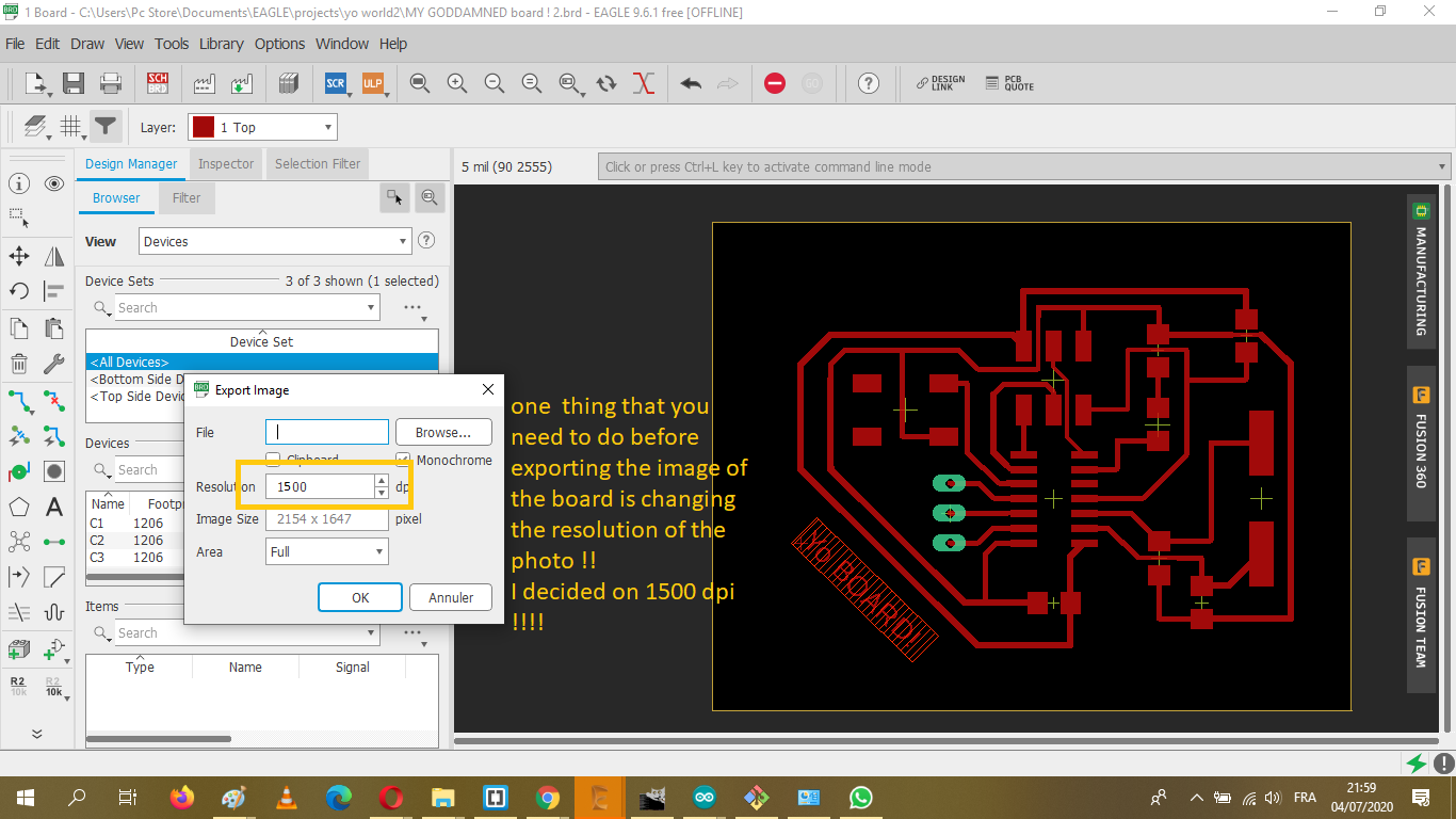
After I saved my work EXPORT>AS IMAGE> (do not forget to click on MONOCHROME too)
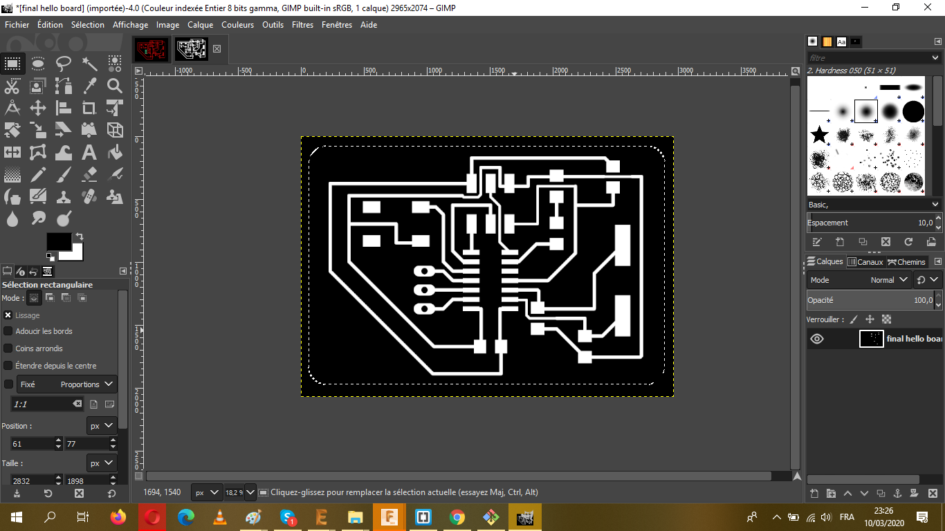
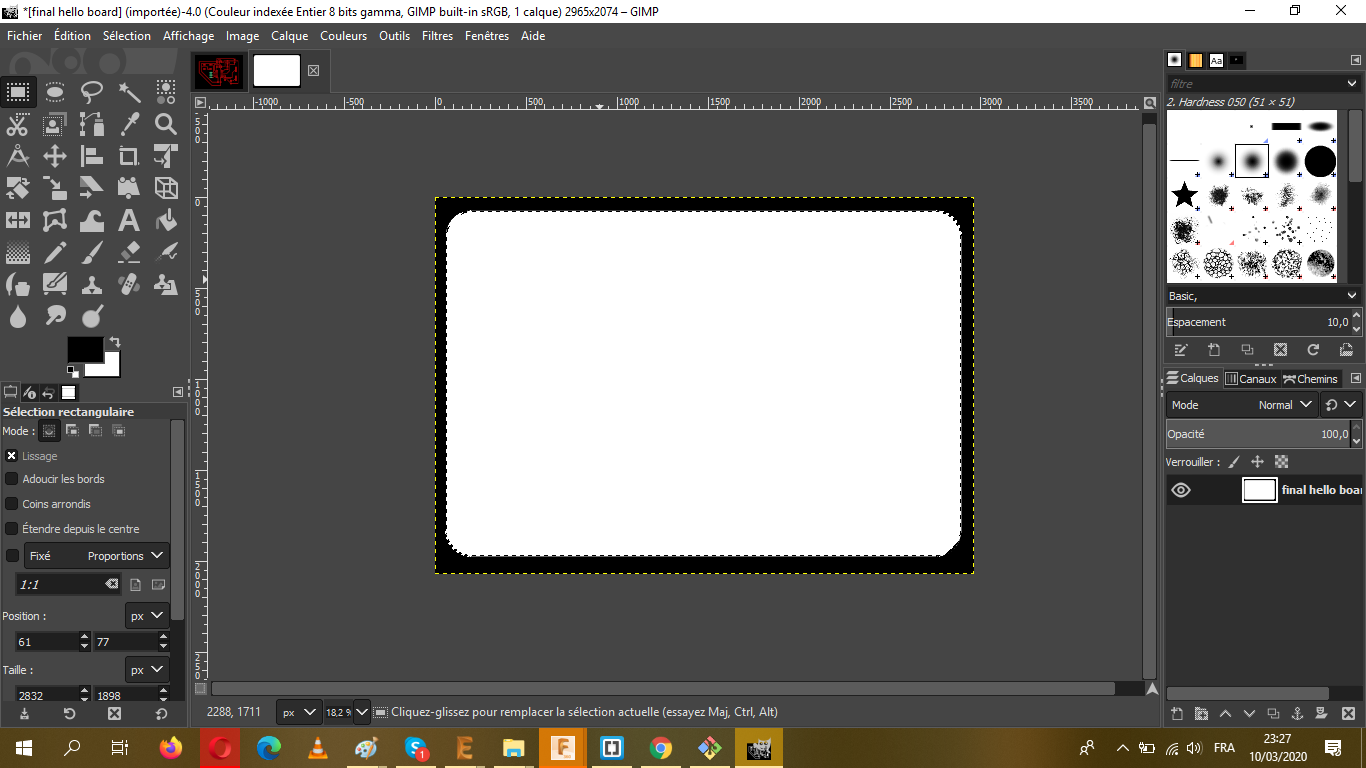
It's now the time for some GIMP work to make the boards cutout
Here's some UPDATES after weeks!!
As I said the the 4th week assignment, because of the COVID-19 and some other local issues we had to delay the work on this weeks, and after the end of the lockdown we had to return to redo the unfinished work, despite the problems that we had, we managed to make the Hello board(period)
Anyway,
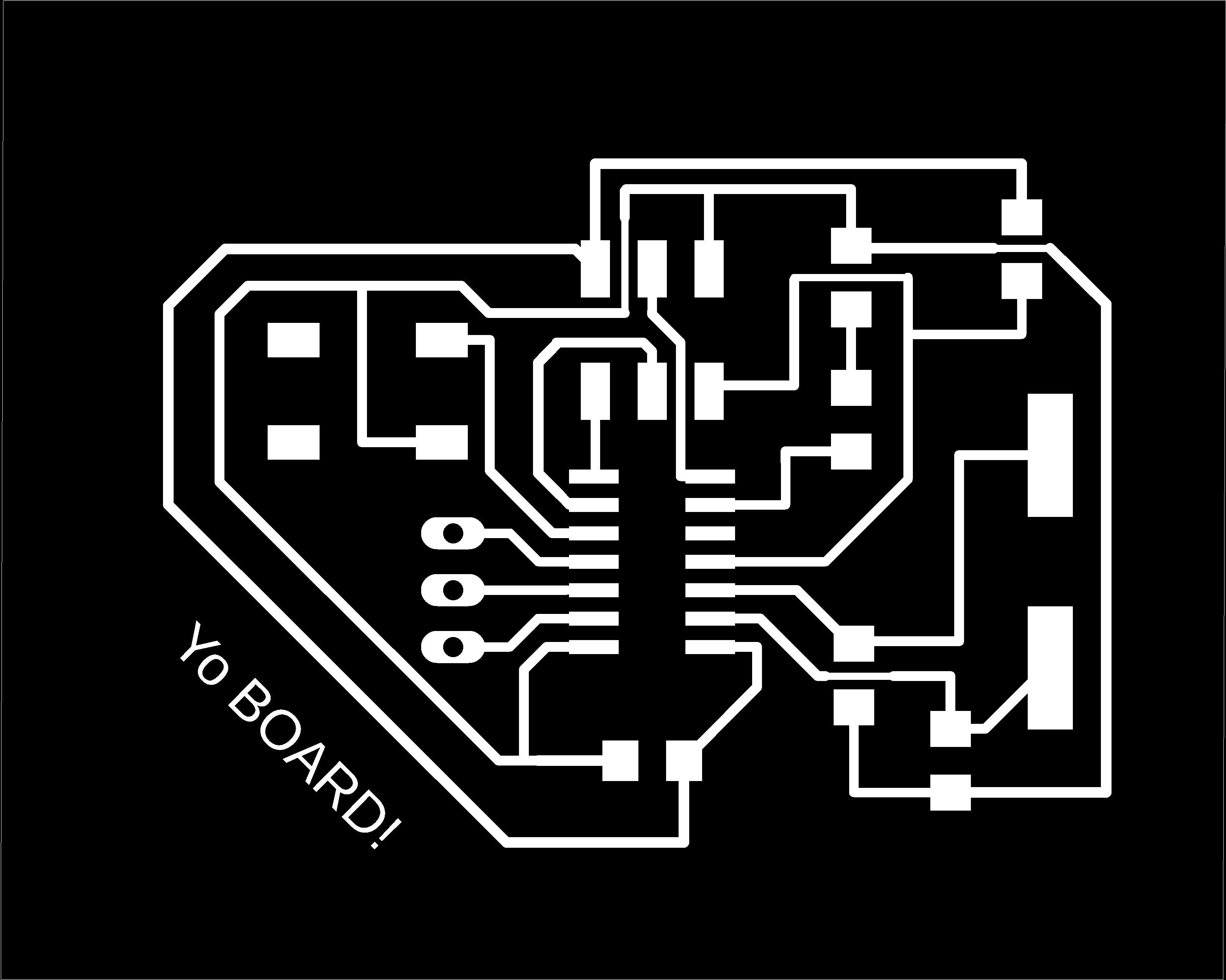
I redid the design and fixed some details!!
.png)
Make the oulines with GIMP and TADA my hello board is done

- Step 3:Uploading the file to the Fabmodule
- Step 4: The milling
- Step 5:Soldering
- Step 6: Programming
It's practically the same as the ISP, the same steps and parameters
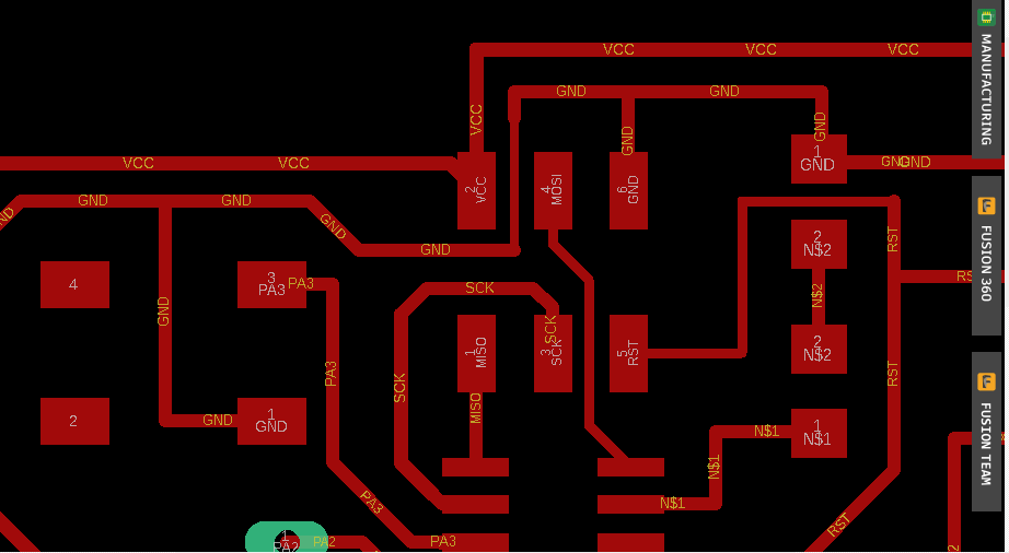
The traces
.png)
.png)
.png)
This was the toughest part 'cause of the lack of the proper tool to mill !!
to finish this part , we suffered alot xD and we broke a lot of endmills!!! However we managed to finish this task
You should take in account some steps before starting to mill
We used a double faced tape to fix the copper plate that we're going to mill the board on it, but we had to be careful to not have any bubbles or empty spots between the tape and the plate before putting it on the work bench (well we placed a 10mm mdf plate to protect it from any scratch);this was for the reason of having a proper balance.
After all, mistakes can take place in this kind of situation so we had to be extra careful!!!
Not only that, since we had some issues with the endmill, we tought about using a thinner plate (0.5 mm).
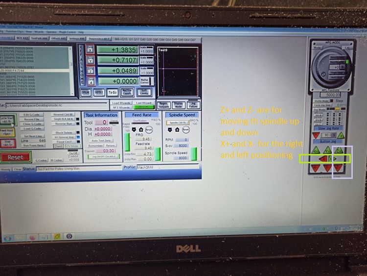
As for the position of the spindle we had to do it "manually" using the X-/+ and Y-/+ features on the Mach3 software!
As for Z axis , we had to move the spindle carefully and lower it slowly until the end of the tool touches the surface of the plate!!
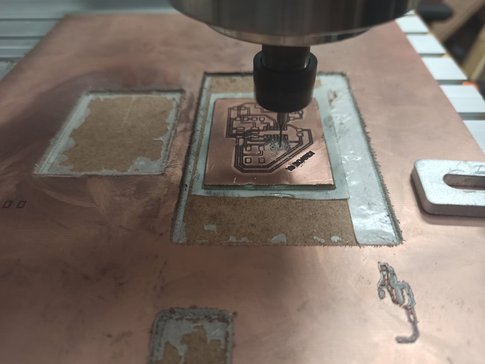
And now all what we had to do, is starting the milling work:
Time for the outlines cutting

and some drill works!!
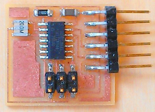
Final result(tho there's some solder work on it)
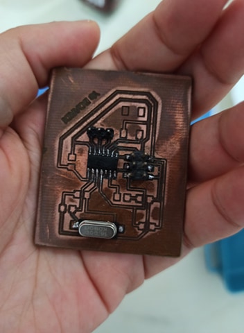
It took some time to finish it, but I managed to solder mine; However I'm still not that good at it xD and since the component are too tiny, we had to pay extra attention
For this part of the work and with the help of our instructor we managed to make it works smoothly~
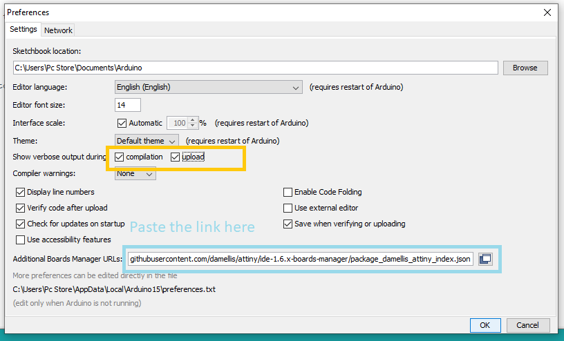
Fisrt of all go to File>Preference and paste this link bellow:
https://raw.githubusercontent.com/damellis/attiny/ide-1.6.x-boards-manager/package_damellis_attiny_index.json
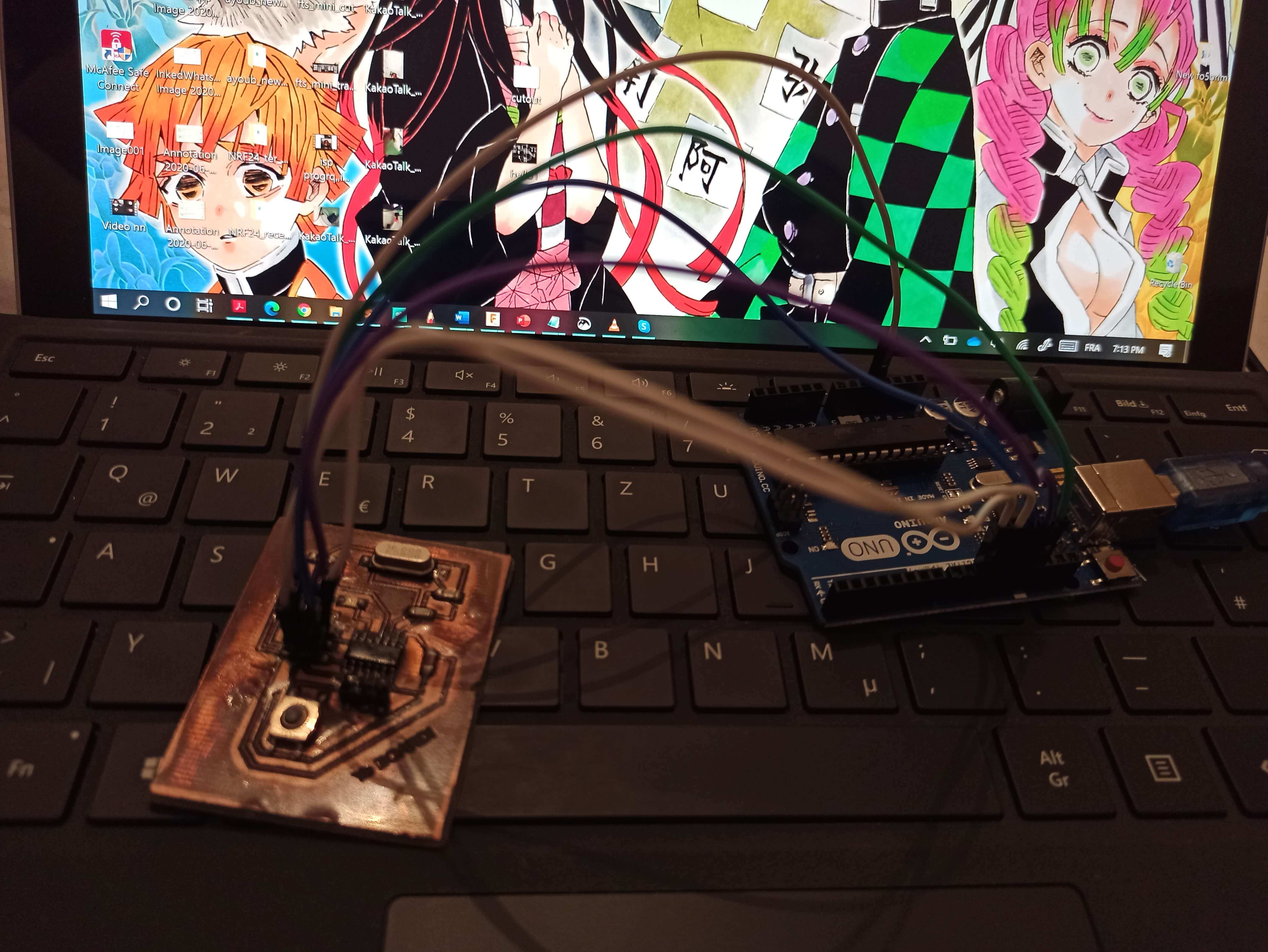
On the other hand , we decided to programm the Hello board using the Arduino and to link both of them by following the instructions bellow!!
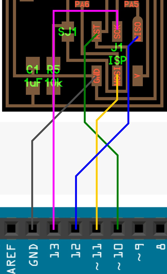
Ps: the Vcc is linked to the 5V of the arduino
Then Tools>burn bootloader
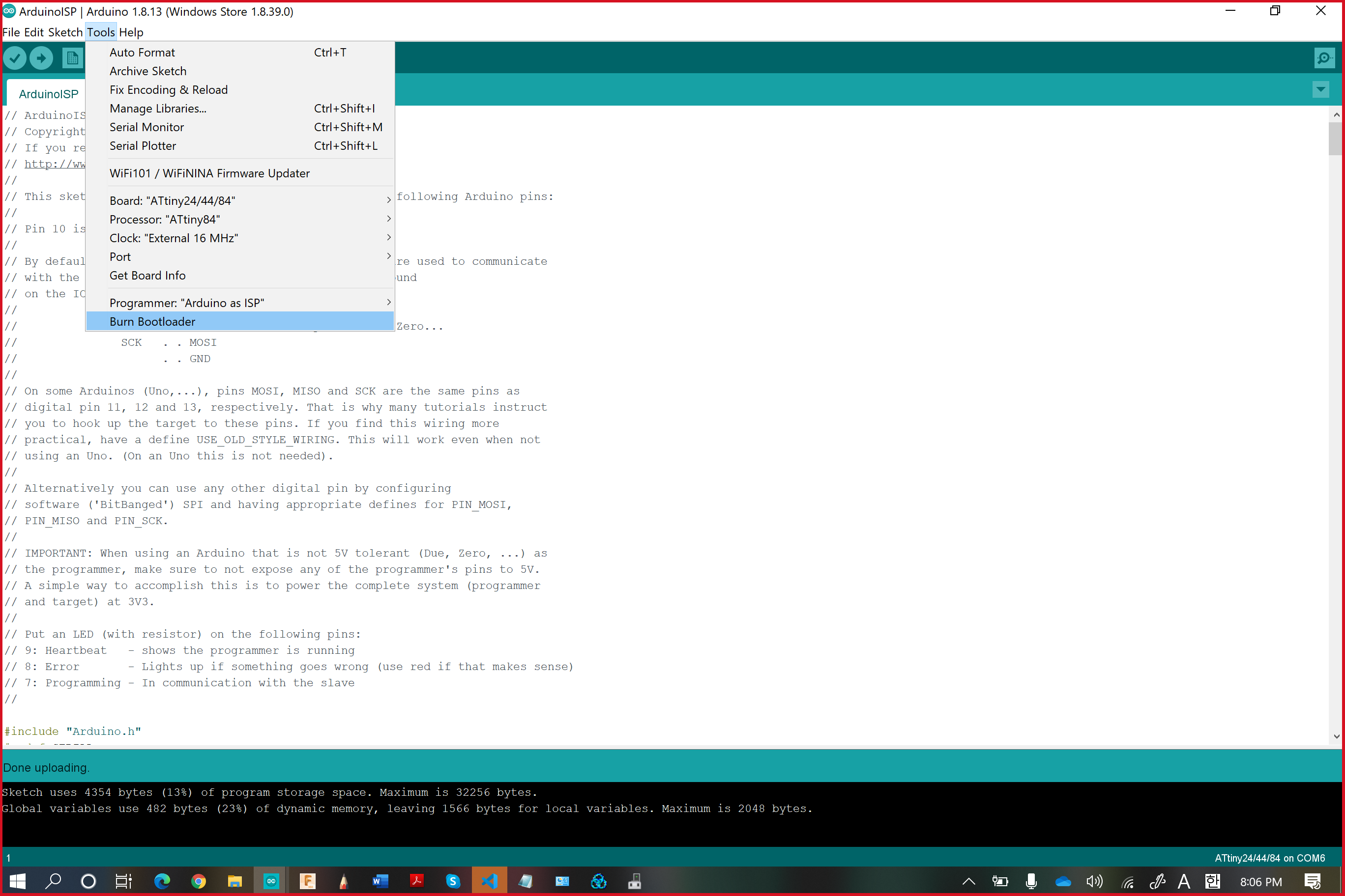
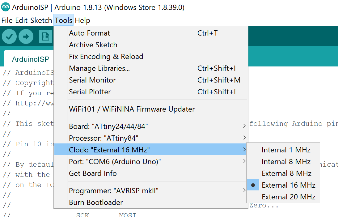
But before that, we had to make some changes
Tools>BoardAttiny24/44/84
Tools>Processor:Attiny84
Clock"External 16MHz"
Programmer:"Arduino as ASP"
And this worked just fine!!
Than go to File>Example>blink
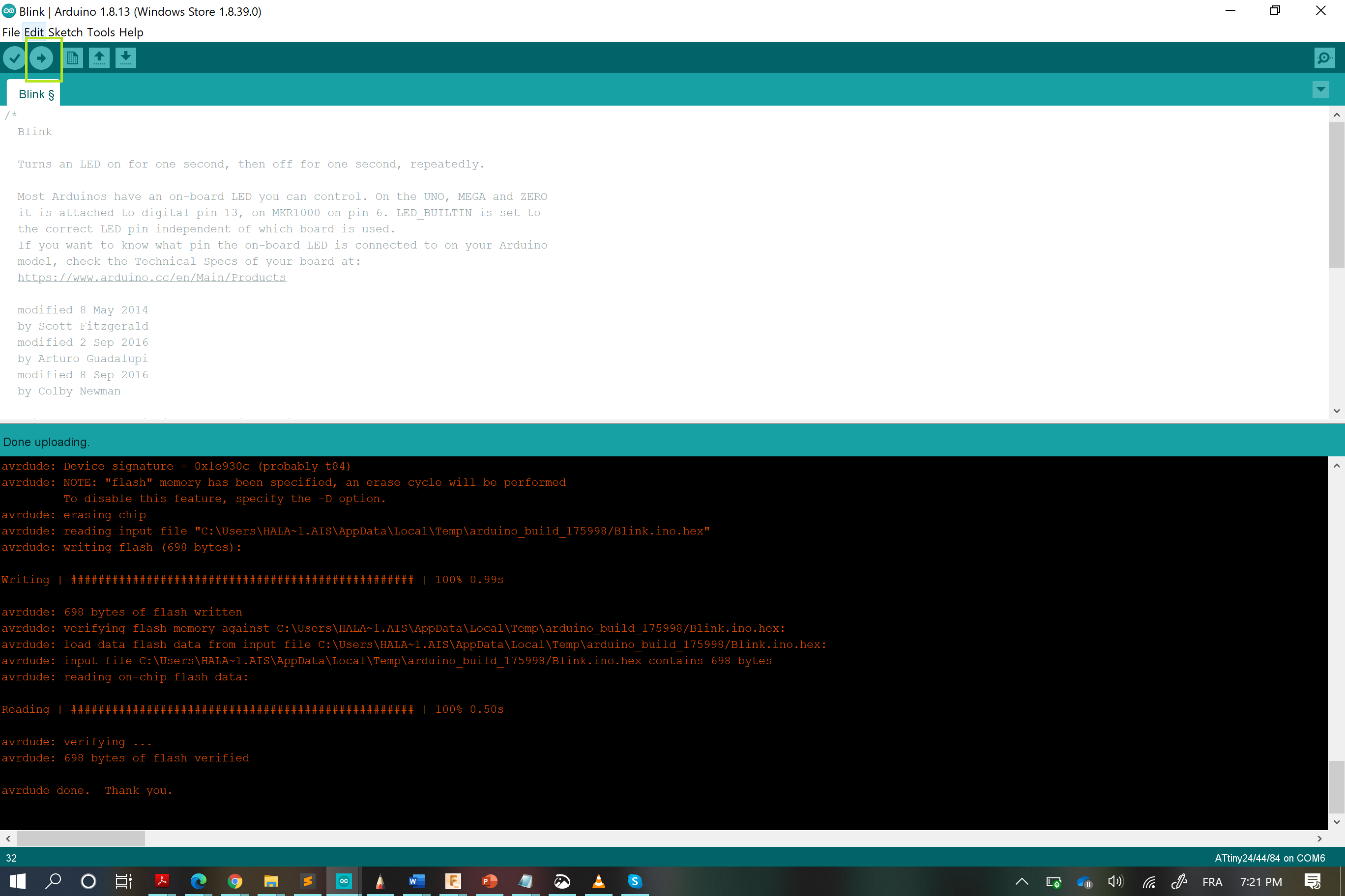
And my board started to blink
My Files
My hello board .brd
My hello board .sch
WHAT I LEARNT FROM THIS WEEK:
- I gotta say that this was the first time that I worked with Eagle , thus this was my chance to learn how to design a board using it.
- Not only that , the milling part (despite the fact that we had a serious time coping with the sudden break of Covid-19, so after the end with the shutdown, we had other serious problem, we spend a lot of time fixing the sittings and the finding the perfect tool for the work to end perfectly), so literally we spend alot of time while setting the X,the Y and the Z axis and changing the bits for traces and outlines(this one has to be bigger in size compared to the traces tool ) cutting.